
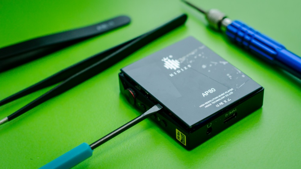
Hidizs AP80 — guide on teardown & repair
10% discount for any item at Hidizs store using our promocode: ZMCR10
![]()
10% discount for any item at Hidizs store using our promocode: ZMCR10
Instead of writing another review, I have prepared something interesting today — an article on how to repair Hidizs AP80 series of DAPs.
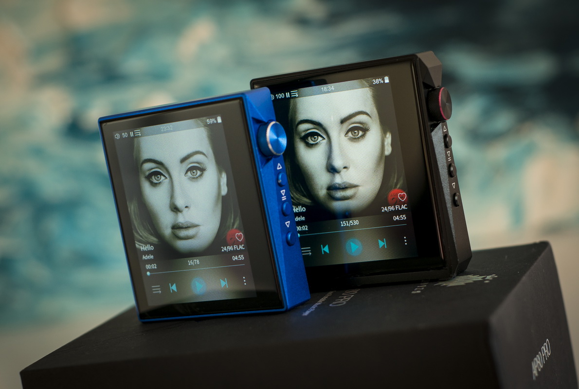
First of all, my Hidizs AP80 (first revision) is in perfectly working condition and remains such since I have received it 2 years ago. During those years it has experienced some heavy usage, acting as a main testing source for numerous IEMs as well as serving its main purpose in everyday life.

I also possess AP80 rev.2 and AP80Pro variants but those were kept on a shelf for the specific tests in future. Unfortunately, future came faster than expected when my beloved AP80 accidently fell on the ground, right lower corner taking all impact force and the screen has cracked.

No visible damage to the aluminum case but the screen glass panel is a mess (had no protective film). As a matter of fact, LCD still works, the image is still there and touchscreen layer is fully operational…
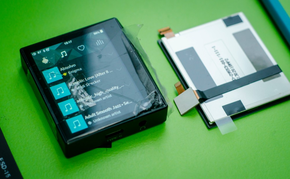
As you understand, using the screen with glass panel falling apart into small peieces is quite dangerous. Additionally, the esthete in me almost panics while looking at the screen in this condition… Therefore, I have decided to restore my AP80 and give it a factory look :)… And I’ve also decided to document this process and combine it in teardown and repair guide for other owners. This guide would also help to understand what AP80 consists of, how to replace battery, screen, jog dial and other elements.
Since changing only glass panel is much more complicated even for the professionals (LCD and glass panel are glued together), the only possible solution is to replace glass+LCD+touchscreen sandwich at once.
Ok, Google. Where to find the spares? No problems here either: I have contacted hello@hidizs.net and requested the price for such repair sandwich. They have stated the price ($19.99) and arranged the order.

Moreover, I also had a talk with Hidizs representatives on the possibility of any customer to request such repair parts. The answer was positive: if you want to perform DIY repair or to hand over parts and broken device to service center nearby — you can contact this email and the person responsible for after sales support would reply with the price and arrange order shipment. Just keep in mind that DIY/unofficial repair would void the warranty. Hidizs is not welcoming such approach but is ready to support their customers with the necessary spare parts if someone doesn’t want or not able to send the device back to headquarters for the official repair.
Anyway, all doubts aside, I was always curious enough to try to fix such devices on my own, not giving a s….t about warranty or the complexity of such task  But at his point I should warn you once more: I would not be responsible for any damage committed to the device by another person in an attempt to fix it while following this guide. Such work requires advanced skills and overall understanding of the process. As for me — I am not a professional but still have large experience in building, soldering and fixing electronics. It originates from many years being involved into radio control hobby and other adjacent activities.
Hidizs AP80 series teardown:
Let’s start with the teardown process. Since there are no screws in AP80 construction, the only way to get inside is either by removing front glass panel with the screen or back glass cover. First is not an option since starting with the screen is always more complicated process that might lead to undesired damage to the most expensive part of the device. Therefore, I would start by removing back glass cover. Yes, it is fragile and the amount of force during this operation should be reasonable. Panel sits on special adhesive and the best (least invasive way) would be the next:
- Heating back panel with a heat gun (even hair dryier would do). Not much, to ~50-60 deg.C.
- Using any fitting suction cups to pull glass panel. You can also try to use any sharp and wide plastic object (like a guitar pickup) to insert between the case and panel in order to separate it. I wouldn’t recommend this method as it may lead to glass fracture.
So, I have successfully lifted heated panel with a special instrument. Quite easy if the temperature is enough to melt the adhesive. Do not apply too much force when lifting this panel as it has Bluetooth PCB antenna attached to the back side and its cable connected to motherboard.

Now we can take a look inside.
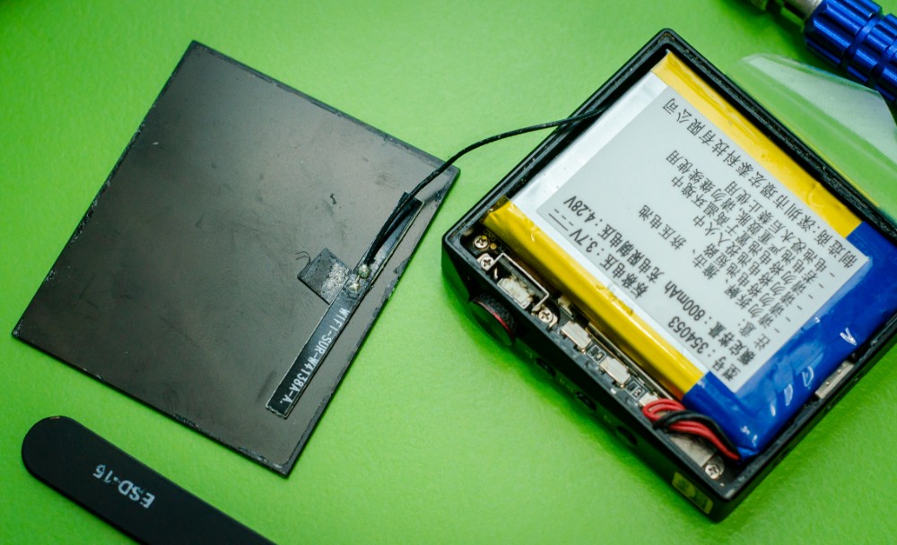
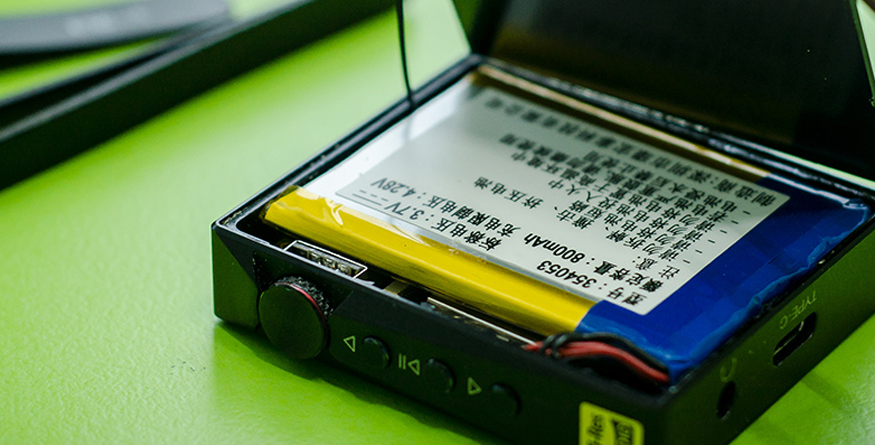
First that we see is 800mAh, 3.7V 1S LiON battery with 4 wires connector which is additionally protected and locked at place by the small aluminum cover with the screw.

Unscrew it first and the next step is to remove the battery.
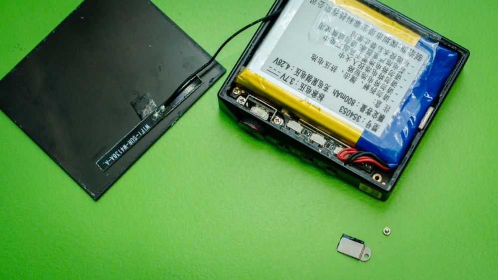
Battery is retained by the adhesive layer applied to the board shielding cover. You can first remove the battery together with this shield (it is held in place by tiny aluminum clips located on its perimeter on the board) and than separate the battery from shield by slightly heating it and inserting thing plastic object in between. But if changing the battery is not among your quests — do not do that and just leave it aside. disconnect battery by gently pulling the wires straightly up near the connector with thin pliers.

Apply even force to all wires at the same time to protect them from stripping or tearing.
The next step is to disconnect Bluetooth antenna from the board.
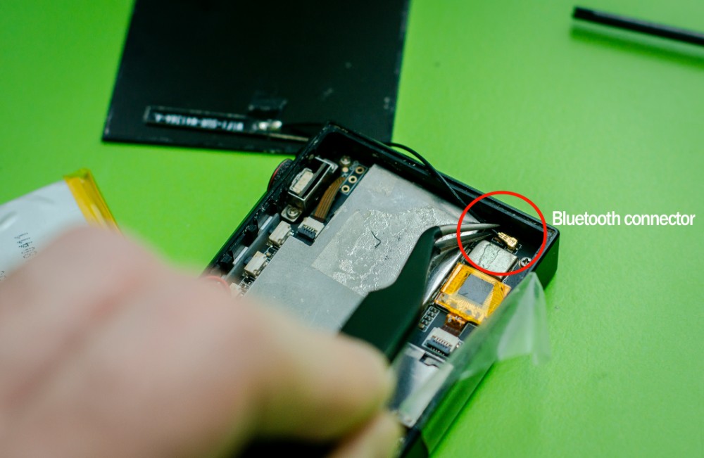
Use small pliers, gently pull antenna cable near the connector to disconnect it from the motherboard.
Than we can remove the motherboard. First, you would have to disconnect all cables from the board.
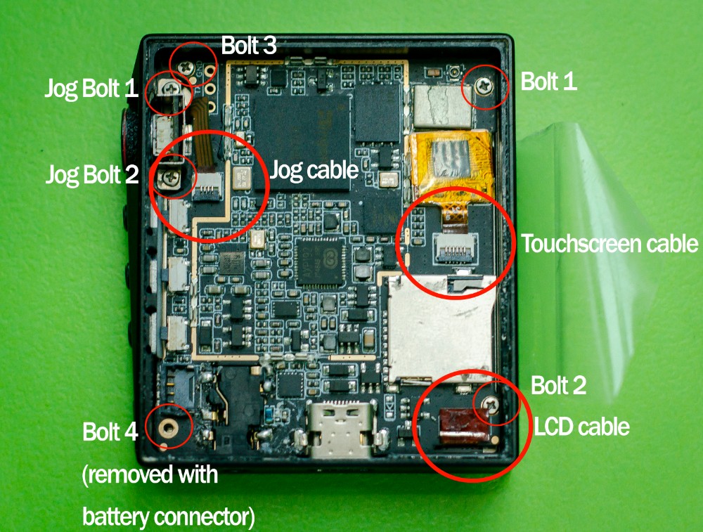
All connectors are covered with black isolation stickers which can be easily removed and applied back later.
Remove:
- LCD cable (by pulling it gently up with the thin pliers)
- Touchscreen cable (by opening connector lock first (move tiny black plastic clamp on this connector from horizontal to vertical position with a toothpick) and gently pulling cable back from the connector housing)
- Jog dial cable (by opening connector lock first (move tiny black plastic clamp on this connector from horizontal to vertical position with a toothpick) and gently pulling cable back from the connector housing)


Now, when everything is disconnected — we can remove all screws and take out the board. Note: be careful with 3 side buttons (Play, Prev, Next) as those are separate aluminum elements inserted into the case openings and held together by a silicon separator.

Also remember that all three buttons are different in length due to such case profile with variable edge thickness. The longer button is closer to the top while the shortest one is at the bottom.

Let’s take a look at the motherboard:

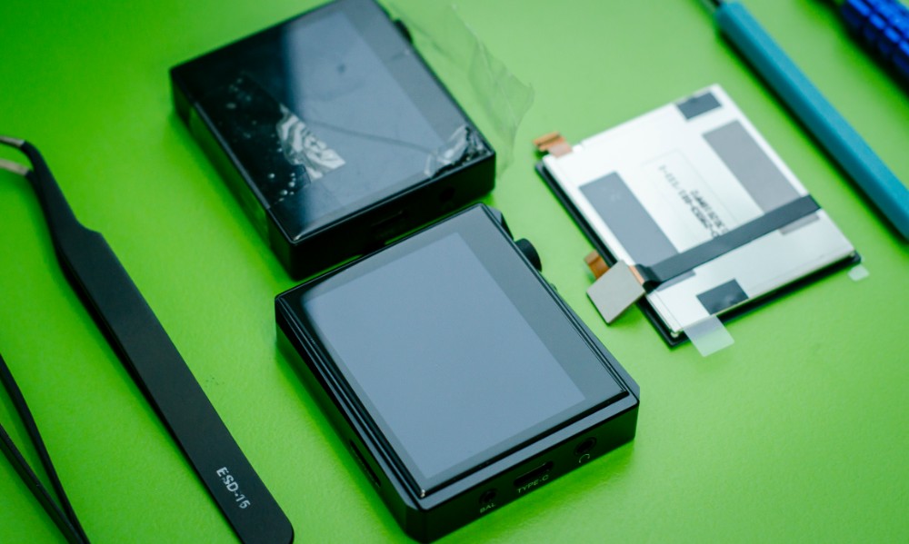
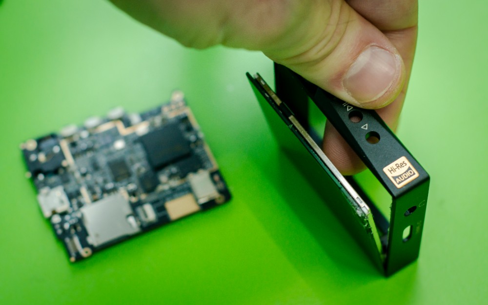
Now, when everything is disconnected we can remove screen sandwich which also sits on the adhesive. Heat it up a little bit and apply reasonable amount of force from inside. It should come out easily afterwards.
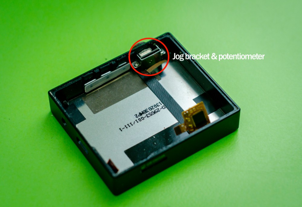
About jog dial. It has the potentiometer on PCB which is additionally retained by a special small aluminum bracket and 2 screws. If you need to replace this jog, besides removing the bracket, you would have to apply some force to lock the potentiometer movement and unscrew its cap from the shaft. The cap is held on the shaft thread with a thread locker, I guess… Again, the best solution to melt thread locker is to heat it. But this is not necessary when changing screen, battery or any other element.
Next important step is installing new screen sandwich and fixing it in place with special adhesive strip or glue. I would use regular resin glue from the closest local home appliance store. We need to remove old adhesive with a help of toothpick and some solvent and than apply thin layer of new adhesive or glue.

My new screen is back in place and what’s left is to assemble everything back in the reverse order.
Don’t forget to apply gentle force when plugging all cables and connectors back, close the connector locks where necessary and apply isolation stickers. Be really careful when fitting shielding back to place. All edges should get in the corresponding clips. Use same process, glue or adhesive strip to attach rear glass panel to the case.

I have also used some stickers to hold front and rear panels against the case to let it dry for 24 hours.

Voila! Everything is up and running. New screen is working perfectly and my Hidizs AP80 is restored to its original condition. Not a big deal and lots of fun during the process…

Hope that this material would help you in case of emergency Wishing you less tremor in hands when repeating the procedure
Many thanks to Hidizs for the goodwill, parts availability and support.
Hidizs official store: LINK
10%OFF for any order at Hidizs store: link
Official Hidizs Amazon store: LINK
Thank you for reading.
Stay tuned, more articles to come!
Amazing work! Detailed description. I wish I had the skills to do this!
I am happy to know that Hidizs is willing to send parts to customers for DIY repairs.
Thanks for your valuable feedback, Pranesh. I would try to make more posts like this in future. Although, this stuff won’t brake down, usually 🙂
waar kan ik een battery kopen AP60Pro